The following text describes all information shown on the Appendix B – Section 27 00 00 Communications PDF found on the Capital Planning Construction Design Documents page.
Appendix B – Section 27 00 00 Communications
Part 1 General
1.01 Description
- All cabling for voice and data will be CAT6. The general building contractor shall provide Inside Plant (ISP) pathways, which may include accessible utility corridors, finished and exposed metal cable tray or ladder, enclosed conduit, duct, or raceway including pull ropes to allow the installation of cable. Junction boxes shall be provided to allow installation of termination jacks at each station. The general contractor shall provide dedicated building closets, equipment backboards, wire management supports, termination racks, a grounding system, and an Outside Plant (OSP) conduit with pull ropes from the Building Distribution Frame (BDF) to nearest manhole.
- University of Maine System Information Technology (UMS:IT) will refer to the cable, which carries Telecommunications System signals, either integrated voice/data or voice only signals, as “voice” cable, i.e. voice riser, voice station cable.
- Inside Plant/Outside Plant (ISP/OSP) bid submittals shall include all costs for construction material, labor and any other items required for ISP/OSP installation.
- The Contractor will be responsible for implementing all ISP/OSP per the design layout and specifications in its proposal. The design of all pathways and hardware shall allow for a 50% growth in capacity. This responsibility includes installation and termination of all ISP/OSP cabling to their proper equipment.
- Particular consideration is to be given to the restoration of penetrated fire and smoke stop partitions and floor slabs to their original condition or to current fire code standards, whichever is greater.
- The Contractor shall furnish blueprints, schedules and other technical data in order to illustrate to UMS:IT the intended method of installation. These shall define material type, path and concealment methods, distribution cable quantities, and room or wall space requirements. This information will be submitted prior to starting any portion of work and is subject to the approval of UMS:IT department.
1.02 Definitions
- Inside Plant (ISP) is defined as intra-building distribution of cable media such as riser cable both fiber and copper coax, station cable, station jack hardware, Intra building Distribution Frame (IDF) terminals, sleeves, conduit, raceways, distribution frame hardware, etc. All other physical plant such as grounding, power, conduit, and raceway not considered OSP are part of the ISP.
- Outside Plant (OSP) are all facilities used to support inter-building connections, including (but not limited to) copper, fiber and coaxial cable, splices, terminators, pairs protection, grounding systems, ducts, conduits, manholes, and all related outside infrastructure. Also included are Main Distribution Frames (MDF) and Building Distribution Frames (BDF).
- Voice Cable – Cabling, which carries Telecommunications System signals, either integrated voice/data or voice only signals, i.e. voice riser, voice station cable.
- Data Cable – Cabling, which carries data communications signals, i.e. data riser, data station cable, data fiber.
- Video Cable – Cabling, which carries video or TV communications signals, i.e. video riser, video station cable, video coax.
- Approved contractor – The bidder shall be Cat 6 certified. Also, must have a minimum of 5 years telecommunications/data installation experience. Cabling technicians must be certified installers. No more than one helper per certified installer. Certification of technicians must be shown if requested.
1.03 References
A. All work shall meet all applicable codes and standards.
- National Fire Protective Association (NFPA) 70.
- Building Industry Consulting Service International (BICSI) Standards.
- National Electrical Manufacturers Association (NEMA) Standards.
- Electronics Industry Association/Telecommunications Industry Association (EIA/TIA).
- UMS:IT requirements.
Part 2 Products
2.01 OSP – Duct System
- The Contractor shall be prudent in the design and installation and use of all available industry techniques to fully utilize individual ducts or raceways and avoid using existing spare ducts or raceways where feasible.
- Each duct bank shall consist of three 4” conduits to each building. The duct bank sizing reflects the installation of video coax, data fiber, and voice cable. Contractors shall install Type C (Carlon 68515WH) and industry approved fittings. One 1¼” three cell maxicell shall be installed in one 4” conduit.
- Where sharp bends or turns are required, prefabricated fittings will be used unless such bends or turns prohibit the pulling of large cables. In such cases, manholes or hand holes shall be installed.
- Rigid conduit will be used where ducts run under roadways. Where conduits are installed in concrete slabs or where the minimum required depth is not feasible. All 4” Rigid conduits will extend a minimum of 10’ past the outside wall and attach to ducts feeding the building.
- The duct systems shall be sloped to permit penetrating water to drain towards the manhole(s). The highest point of the duct array will be at the building entry point. All duct systems will be marked with the appropriate marking tape on top. There must be a minimum of 4 inches of sand above the conduits before backfilling.
- All unused ducts shall be provided with removable conduit plugs or equivalent for waterproofing and protection. All ducts shall be cleaned of earth and debris, and equipped with minimum 200-pound strength pull rope.
- All cables entering ducts shall be sealed according to industry standards and provide a watertight seal.
2.02 Manholes and Hand Holes
- New manholes shall be reinforced concrete construction, cast-in-place or pre-cast, and must meet industry standards for telephone manholes.
- The manholes/hand holes sizes shall be a minimum of 4’ x 4’ x 4’, up to a maximum of 6’ x 12’ x 7’ (see manhole/conduit drawings for manholes sizes and locations).
- A PVC water barrier shall be installed at each construction joint.
- Maximum distances between manholes and from manhole to buildings shall not be great than 600 feet for a run containing an aggregate of a 45-degree bend and 400 feet for runs having an aggregate of a 90-degree bend.
- On straight sections maximum distance between manholes shall be no greater than 600 feet.
- Manhole lids will be permanently marked with the word “Telecom” or “Communications.”
- Each manhole must have an integral 7/8” inch steel ring 6” diameter as part of the manhole structure. A 12-inch circular sump hole must also be included at the lowest point in a manhole.
- All manhole covers must meet industry standards for vehicular traffic loads.
2.03 Trenching, Back-filling and Restoration of Grounds
- Trenching shall be done using trenching machines or backhoes and supplemented by hand excavation where required in order to avoid utility disruption.
- Ducts shall be placed on top of four inches (4”) of sand bedding at the bottom of each duct run. An additional four inches (4”) of sand shall be placed around and between ducts. A final four inches (4”) of sand shall be placed on top such that an aggregate of twelve inches (12”) exists from the floor of the duct trench and the top of the last four inches (4”) of sand.
- Below finished grade, just on top of the final layer of sand, and offset from the center of the duct bank, the Contractor shall place one (1) continuous plastic marking strip labeled “Communications.”
- Gravel backfill shall be used in paved areas and earth shall be used in lawn area. Backfill shall be free of large stones of 3” in diameter or greater.
- All backfill materials shall be compacted 95%.
- The Contractor shall repair all the University grounds and property to their pre-construction condition using materials of same or better quality. This includes, but is not limited to, re-paving, re-seeding, walls, fences, landscaping, utilities, signs, painting, curbing, etc.
- Bituminous materials should be used where necessary for repairing roads, parking areas, and footpaths. The materials shall be provided in two (2) courses: two 2” binders and a 1” surface course. All existing paths and roadways of greater depth shall be repaired to match existing materials and depths.
- UMS:IT reserves the right to inspect all materials to be used in the process required in this section on trenching, backfilling, restoration of grounds, and to demand changes in type and quality in order to meet UMS:IT standards. Such changes will be at the Contractor’s expense unless UMS:IT requires materials of a higher quality than originally required by this document. In all cases concerning determination of “original condition”, UMS:IT will be the judge and have final approval.
- Trench depth, from the bottom of the trench to the top of finished grade will be three feet, eight inches (3’ 8”) under pavement, and two feet, two inches (2’ 2”) under finish grade.
2.04 Cable Identification And Labeling
A. After final acceptance, Contractor will prepare and submit cable OSP drawings. These site drawings will be supplied on reproducible materials, and the Contractor will add its distribution system and show at a minimum:
- Exact route of total outside plant including trenching routes.
- Depth of cable trench.
- Locator coordinates measurements from cable location to nearest building.
- Cable number, cable pair count, wire gauge, cable lengths, and cable types of every OSP copper, coax and fiber cable included in the system.
2.05 OSP Cable Sizing
A. Contractor will design an OSP that is complete.
- All OSP pairs must be terminated in Northern 191 or CIRCA #2200B-100 fuse protectors.
- All fiber cable shall be Hitachi 12 multi-mode 62.5/125 and 12 single-mode fibers or as specified.
- All cable shall be rated for outside usage in duct systems.
2.06 Cable Type, Splices and Protection
- All Copper cable used in OSP shall be waterproof with moisture and heat resistant properties up to 125 degrees, Gel-Filled Core Duct/Direct Burial type, with a Metal Clad composition. All wire shall be Twisted Pair type PE89 jelly filled 24 AWG solid copper cables.
- All splice connections in manholes shall be placed in re-enterable waterproof closures and sealed according to manufacturer’s specifications. All splices shall be made with 3M modular connectors (4000-D) and enclosed in “Preform” enclosures.
- All OSP will be properly grounded according to National Electrical Code (NEC) Codes and Building Industry Consulting Services International (BICSI) Standards, and Local Codes and industry standards. All ground connections are subject to the inspection and approval of the UMS:IT, as well as State and Federal Inspectors.
- All OSP will be enclosed in conduit or raceway where appropriate, such as required by Fire Codes, exposed to steam pressure relief valves, or in public areas.
2.07 Administrative and Academic Building OSP Data Fiber Sizing
- Fiber cables shall be pulled to the Building Distribution Frame (BDF).
- All fiber cables shall be properly terminated at the BDF.
- In the fiber installation there will be no splices in the fiber cable, other than those at termination points.
- All fiber cable shall be Hitachi 12 multi-mode 62.5/125 and 12 single-mode fibers or as specified.
2.08 OSP – Video Cable Specifications
- All video cables for OSP will be Hitachi single-mode fiber.
- Video fibers shall terminate on SC/APC fiber optic connectors.
2.09 Configuration and Specifications for ISP
- Where existing sleeves, riser conduit, etc., are insufficient for new riser cable, construction of new sleeves, cores, and conduit or raceway shall be proposed and included in the contractor’s purchase price. A minimum of twelve inches is required between all phone/data services and any electrical circuits. This is a UMS:IT requirement.
- There must be a 50% growth factor built in on all conduit runs used for Voice, Data and Video jacks. Minimum conduit for station runs will be 1” trade size conduit with proper fittings. A 1” NMT non-metallic tubing properly installed meeting all NMT requirements of NEC/BISCI and the University of Maine is also acceptable. There will be no daisy chaining of jacks for any reason. A pull string needs to be installed in all conduits used for ISP/OSP cabling.
- Open Ceiling – All conduits will be installed above the tray or back to the proper intermediate distribution frame (IDF)/BDF.
- Suspended Ceiling – All conduits will be stubbed above the ceiling or back to proper IDF/BDF. Install B-Line cable tray in all corridors providing a continuous pathway back to the proper BDF/IDF.
- All old cables are to be removed as required by the NEC.
2.10 Cable Routing
- It is mandatory that the contractor makes use of and provides cable pathway materials between all building main distribution frames (MDFs), BDFs or IDFs. A 50% growth factor must be provided when a job is completed. A minimum of 12 inches shall be kept between all data and electrical pathways when being designed (UMS:IT requirements).
- Such pathway materials may include:
1. Finished and exposed metal cable tray, ladder, or raceway.
2. Enclosed conduit or wireway through walls or ceiling plenums.
3. Sleeves and conduit.
4. Other materials as the contractor may require. - Provide B-Line – Part # FT2X12X10. Must be mounted no more than 12” above suspended ceiling, or 8’ 6” in open corridors. A usable pull string is to be left in each cable tray on completion of cable installation.
- It should be noted that UMS:IT will not supply pathway materials.
- All raceways used for Telecom/Data shall be Panduit. They shall be sized properly for use. Only proper fittings for raceway shall be used.
2.11 CAT 6 Requirements and Parts
- All data cables shall be CAT6 Hitachi part # 30212-8.
- All data cables installed shall be Hitachi part # 30212-8BL CAT6 with a PVC jacket being blue.=
- All dorm jacks shall be installed at 33” to bottom.
- All E&G building jacks shall be installed 16” to the bottom.
- All CAT6 cable shall be installed according to the NEC code, BICSI standards and EIA/TIA standards.
- All CAT6 cable shall be installed on blue Hitachi part # 30212BL and terminated on Panduit jacks, part # CJ688PBB.
- All CAT6 cable shall be 23 AWG and 8 conductors terminated as 568-A standards allow.
- All raceway installed to be used for CAT6 installation must meet all BICSI standards as well as ANSI/TIA/EIA standards.
- Cables shall terminate in proper Siemon part # HD6-24B-SIE patch panels rated for CAT6 specs, RJ45 faceplates with 110 terminations on back.
- Patch cables rated for CAT6 100mb are to be supplied and installed.
- CAT6 certification must be received prior to final payment.
- Velcro required to tie and support cables.
- All raceways for IT shall be properly sized for Panduit or 1” conduit.
2.12 Distribution Frame Requirements
- New IDF and BDF room construction shall be included in Building Design blueprints.
- There shall be included, in the building, an equipment room as designated by UMS:IT strictly for data telecommunications. All BDF and IDF rooms shall be a minimum of 8’ x 10’ x 8’, with signage indicating that the room is a data telecommunications facility.
- An IDF room will be required per floor in order to keep distance requirements for CAT6 wiring within specifications. This room(s) shall be keyed to the telecommunications master key. A 50 pair feeder cable for voice shall be run to the BDF room from each IDF room. These cables should run in pipe chases of 4” conduits. A 12/12 fiber riser cable will be run from BDF to each IDF for data feed. BICSI and NEC standards and UMS:IT requirements must be met. RJ11 coax shall be installed to each IDF from the BDF. Air temperature and air movement should meet office requirements for the building.
- BDF/IDF rooms should have a switched light with 50 ft. candles available and at least two isolated duplex outlets rated for 20 amps. A covered # 6 copper ground wire and bus bar must be installed at each IDF from main grounding frame in BDF and from racks installed at each IDF/BDF.
- A # 4 copper ground wire, properly installed and terminated, will be required in all BDF rooms, part # SB477K.
- Two 4” conduits from BDFs to IDFs with pull strings installed.
- Three 4” conduits feeding BDF from OSP manholes.
- All conduit, raceway, coring, and equipment backboards must be supplied and installed by the Contractor.
- Contractor will be required, prior to start of project, to submit a floor-by-floor list of where new BDFs and IDFs will be required.
- No sprinkler heads should be installed within the BDF/IDF rooms. Heat/smoke detectors should be installed where necessary for fire code compliance.
- All cable will be marked clearly and legibly at both ends.
- All cables and fiber shall be terminated on a 7’ x 30’ x 19’ rack. All installed equipment shall meet all BISCI requirements as well as UMS:IT requirements. All racks shall be properly bonded to ground bar in IDF/BDF rooms.
- One wall having a 4’ x 8’ x 3/4” sheet of plywood attached painted with fire retardant paint is required in the BDFs and IDFs. Plywood should be vertically mounted behind the racks installed 2’ off the finished floor.
- Wire management hardware located on three (3) walls above the racks is required in preparation of installation of termination equipment by the contractor (see diagram included in this document BDF/IDF requirements closet).
- Single-mode fiber will be fusion spliced to factory ceramic SC and SC/APC pigtails.
- Multi-mode fiber will be terminated using ST Unicams factory polished ceramic.
- All fiber patch panels are to be Seicore, sized to accept fibers from the OSP plant as well as riser for the IDFs.
1. Data telecommunication rooms (including but not limited to BDF and IDF closets): The BDF closets shall be on the lowest floor level of the building being served. An IDF closet is required for each floor above the lowest floor.
2. All BDF/IDF closets shall be designed as shown in the diagram below. Materials for this requirement are shown in the diagram.
3. All data telecommunication rooms must have a 3’ door swinging out into the hallway.
4. All data telecommunication rooms are for INFORMATION TECHNOLOGIES USE ONLY; any other equipment needing IT service should be located in a separate mechanical room.
2.13 Cable Support and Rack Products
- All material to be installed to product specifications.
- All material to match cable trays installed in the building.
- All racking and cable tray to be grounded with # 6 green PVC ground wire.
BDF/IDF Requirements (Example using B-Line and (SB) hardware)
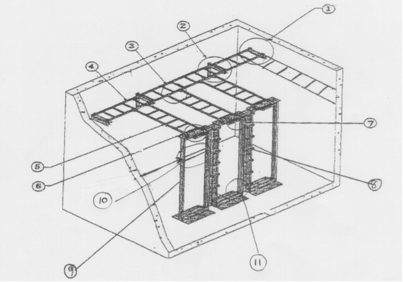
| Item Number | Description of Item | Item Part Number |
|---|---|---|
| 1 | End Bracket Relay Wall Bracket | SB87019S2FB |
| 2 | Runway Wall Bracket | FTB12CS |
| 3 | 90 degree Splice Bar | 90DEGREE KIT |
| 4 | Fast Splice Bar | FTSTLC |
| 5 | Cable Runway B-Line | FT2X12X10 |
| 6 | Splice Washer Kit | WASHERSPL KIT |
| 7 | Runway Termination Kit | SB-2105-12-TG |
| 8 | Copper B-Line Vertical Management | SB57166D084AL |
| 9 | Copper B-Line Aluminum Rack | SB556084XUAL |
| 10 | Horizontal Management | CMPHH2 |
| 11 | 20 AMP Dedicated Electrical Outlet | – |
Note: Wire management required around each frame: top, bottom and side. This will be sized to fit each building requiring size changes to match density and count of building. All products and fittings are B-Line Cable Tray and fittings.
2.14 Cable Networks Identification and Labeling
- Each contractor shall permanently mark all cables with permanent labels.
- Labels shall be waterproof materials with indelible text information and mechanical attachment or waterproof adhesive.
- Each required label location shall contain all fields of required information below.
- Required identification information shall include the following items, combined to produce a unique and non-duplicating identification for each cable. No two jacks within the cable plant shall have the same number.
- Jacks shall show termination location; floor location and BDF/IDF location (i.e. basement – BDF A001; 1st floor to IDF B101; 2nd floor to IDF C201).
- Where multiple cables have the same termination location and floor identification number, the contractor shall add an alpha/numeric suffix to provide non-duplicating identifiers (i.e. A201, A201B).
- All jack locations should run straight back to the equipment rooms or cable trays in their own raceway.
- Equipment rooms should have a switched light and at least two duplex outlets rated for 20 amps.
- Pull strings are to be installed at the time of construction in all conduits.
- If utilized, pull strings must be replaced prior to completion of project.
- Cables need to be toned and correctly labeled at the time of installation.
- Riser fiber cable shall be 12 strand multi-mode and 12 strand single-mode fiber.
- Cables for voice and data shall not exceed 290’ end to end.
2.15 Uniform Wiring Plan (UWP)
- Below are the jacks and symbols to be used by the contractor when cables and terminations are installed. Panduit jacks and equipment will be used. All jacks will be wired as 568A and meet CAT6 certification.

- UWP#1s – Consists of three separate cables (23 AWG), 2 blue data and 1 RG6 coax. (See symbol 1 above).
- UWP#2s – Consists of two separate cables (23 AWG), 2 blue data, these are the standard for all offices. (See symbol 2 above).
- UWP#3s – 1 blue voice cable only (23 AWG). This jack is used for alarm circuits mostly. (See symbol 3 above).
- UWP#4s – 1 blue data cable (23 AWG). Used where no phone will ever be needed but data transmission is required. An example would be an in-house billing system, i.e. Harco. (See symbol 4 above).

2.16 Voice and Data Cable Specifications for Horizontal Cabling
- Cables will be 23 AWG 8 conductors Unshielded Twisted Pair (UTP).
- All cables will be blue category 6 four pair and comply with EIA/TIA 568A standards.
2.17 Video Wiring Plan (UMP)
- The contractor must install F59SSV quad shielded RG 6 type drop cables for subscriber loop locations. RG6 type subscriber drop cables are used to interconnect the TV outlet with multi-tap devices that will be installed at the BDFs or IDFs.
- At the outlet, the contractor shall terminate the cable in the outlet connector using an F10F10S11-X straight jack. The TV outlet shall then be terminated using a 75-ohm F terminator.
2.18 Video Riser Cables
- Where video riser cables are required between floor types F11SSEF and single-mode fiber will be installed.
- Routing of video riser cables follows voice cable installation from floor to floor.
2.19 Wireless Networking Requirements
- One (1) 1” conduit run to each location for networking cables.
- Conduits will terminate either at BDF, IDF or above the cable trays with CAT6 data cable being installed.
- All ANSI/TIA and NEC codes or requirements must be met.
2.20 Camera Installation
- A 1” conduit from the camera location back to the cable tray or above suspended ceilings.
- Conduits will terminate either at BDF, IDF or above the cable trays with blue CAT6 data cable being installed.
- A blue CAT6 data cable shall be installed and terminated in an RJ45 Panduit jack.
- Jack shall be labeled to show proper BDF or IDF location, i.e. Jack A1001 for BDF or B2001 for IDF.
- Cameras to be used are axis 216FD for fixed dome inside installation.
- Outside cameras are to be axis and will be listed by their needs. Recommended part # AXIS 223M, Outside Housing recommended part # AXIS #24889, including heater and blowers.
- NUV for each building to be installed in BDF rooms equipment rack, part # 1PNUR1UST4TB8R must be able to record for 28 days.
2.21 Outside Emergency Phones
- Two 1¼” conduits run to pedestal location, 1 for Telecom/fiber cables, and 1 for electrical circuit to be installed with ground fault interruption 20 Amp minimum 120v rated. Each to be terminated in the proper equipment rooms, i.e. electric to electric panel, IT to proper BDF room.
- 1¼” conduits need to be rated for outdoor use, PVC schedule 40 recommended.
- Symbol for location(s) is:


2.22 UMS:IT Voice and Data Cable Specifications for Jacks
- All cables are 23 AWG 8 conductors unshielded twisted pair cable.
- Category/Level 6 – cable must be 8 conductor and comply with EIA/TIA 568-A standards.
- Color-coded with a blue PVC jacket.
- DC Resistance 9.38 @ 100 meters.
- DSC Resistance Unbalanced 5% maximum.
- Impedance @ 250 MHZ 100 + 15%.
- Category/Level 6 – When requested for installation, specs will be given and approval from Telecommunications on the cable to be installed will be given.
- Characteristics:
- Propagation Delay @ 10 MHZ 5.7 per/meter.
- Delay Shew @ 25NS/100 meters.
- Attenuation crosstalk 11.4 db @ 250 MHZ.
- Specifications:
- Blue PVC jacket.
- 8 Conductors 23 gauge.
- DC Resistance 9.38/100 meters.
- DSC Resistance unbalanced 5% maximum.
- Pair to ground capacitance unbalanced maximum @ 1 KHZ 100m.
- Transmission Properties:
- Freq 427.0.
- Maximum attenuation @ 20 deg. Celsius 50.5.
- Near end crosstalk worst pair combination 64-15log (F/00.772).
- Power Sum N/A.
- Worst Pair SRL 10 db.
- Resistance OHMS 100 l15%.
2.23 Install Level 6 Standards
A. ANSI/TIA.E1A 568A Category 6 E (400 MHZ):
- 155 mbps ATM and 100 mpbs Ethernet.
- 4 pair 23 gauge copper.
- ISO/IEC 11801.
- Min Bend Radius .820.
- PVC Blue Jacketed.
- Cable markings starting at 0 to 1000’ per box.
- Non Plenum 75N4.
B. Electrical Testing Laboratories (ETL) Verified Electrical Performance:
- CAT6 Standards:
- Input Impedance 100 ohm + 15 ohm 1-100 MHZ.
- Capacitance 4.6 NF/100 m nominal.
- DE Resistance/Unbalanced 6.66 ohms/100 m max.
- Propagation Delay 5.7 N/SEC/m mac at 10 MHZ.
2.24 Test Records for ISP/OSP
- Contractor will test each OSP pair in each cable on an end-to-end basis after terminating. Maximum allowable defective pairs will be limited to 1% of the total number of pairs and a maximum of one (1) pair per 25-pair binder group. Defective pairs over 1% will require cable repair or replacement at the Contractor’s expense.
- ISP testing for each station cable is required with zero defective pairs acceptable.
- The Contractor, at no cost to the University, will replace cables rejected by the UMS:IT department with new cable from end to end.
- Records of testing will be delivered to UMS:IT in MSExcel format, or software that is compatible with MSExcel.
- Building will not be accepted for service prior to records being received, thus no service will be provided.
Part 3 Execution
3.01 OSP – Fiber Installation
- No splices will be allowed in OSP fiber. Any faulty cables must be replaced at Contractor’s expense.
- All fiber cable must be installed in accordance with manufacturer recommended tensile specifications.
- Lubricant must be used when installing fiber cable. This lubricant must be manufacturer guaranteed to be non-destructive to the cable sheath or any portion of the inner duct.
- All fiber cables shall be terminated in an approved Lynn patch panel using approved ST, SC or SCAPC connectors. All connections shall be fusion splicing onto correct connectors. Labels shall show the destination of each fiber optic strand.
- All fiber cable will be tested for loss and bandwidth according to the manufacturer’s specifications. Tests shall be performed after all the cable has been installed, spliced and terminated.
- All fiber cable shall be 62.5/125 multi-mode or hybrid Hitachi/Corning Fiber containing twelve multi-mode fibers and 12 single-mode fiber rated for outside usage in duct system.
3.02 OSP – Data Fiber Installations
- Specifications for Altos/Lst Cables:
1. Maximum attenuation: 3.5/1.0.
2. Minimum bandwidth: 120/500 850 MHZ to 1300 MHZ.
3. Gigabit Ethernet Distance Guarantee 500/1000.
4. Multi-mode/Single-mode.
5. Graded Index: 50 Gigabit Plus CL.
6. 62.5/125 micron core diameter (+/-3).
7. Maximum Tensile Loading: 600 lbf. - The Contractor is responsible for installation and testing of fiber. A loss of more than 2dB is not acceptable.
- All fiber cable must be installed in accordance with manufacturer recommended tensile specifications.
- All fiber cables shall be terminated in an approved patch panel using SC ceramic ferrule connectors. Single-mode fiber must also be properly terminated and marked using SC/APC or SC pigtails, both need to be fusion spliced. Labels shall show the destination of each data fiber optic strand.
- All fiber must be tested prior to installation with an Optical Time Domain Reflectometer (OTDR) to insure cable integrity and to identify any damage due to shipping. An OTDR graph must be delivered to the University prior to the installation of the fiber cable and after the cable has been installed.
3.03 Data Fiber Testing
- All fiber cable must be tested to guarantee the performance integrity of cables, bends, tensile loads and terminations or cross connects.
- Each fiber cable must be tested for loss and bandwidth. Tests shall be performed upon completion of installation and termination.
- Any cable that is found to be defective shall be repaired or replaced at the contractor’s expense.
- An OTDR graph must be provided for each fiber strand tested.
- Testing must be accomplished with an OTDR.
3.04 Inside Plant (ISP) Installation
- The cable will be less than 280 feet from station jack to distribution frame termination.
- All cable paths that will be used for Category 6 cable installation must meet all applicable codes, BICSI and ANSI/TIA/EIA standards.
- When a cable must be created in an existing building, the following concealment methods are acceptable:
1. Dry wall: fishing of hollow wall cavities.
2. Plaster or Tile Wall: Color coordinated wire mold.
3. Drop ceiling: Velcro every 10’ and avoid lighting fixtures and all electrical conduit and raceway.
4. Utility Corridors: Concealment not required; Velcro every 10’ to (chases and trays) to self-supporting hangers, avoid receptacles and all electrical conduit/raceways. Clear and free conduit or riser sleeves are available for use wherever they are found and should be used first.
5. Raceway shall be installed where indicated and when required to run on the surface of a wall. Raceway shall be Panduit and must be properly sized and meet the installation requirements of the manufacturer of the cable to be installed.
End of Section 27 00 00
(Revised October 15, 2014)