The following text describes all information shown on the Appendix C – University of Maine Campus Design Criteria PDF found on the Capital Planning Construction Design Documents page.
Appendix C – University of Maine Campus Design Criteria
The following is a list of items that the University of Maine has developed as an indication of the expected level of quality for equipment, materials, and procedures. These items are applicable to the extent they are relevant and appropriate to the project being undertaken.
The University of Maine requires that the design comply fully with all applicable codes, accessibility requirements, regulatory permitting, and municipal code office reviews. The design shall not, however, require additional project resources to exceed these standards.
At each stage of the design process, the University shall be provided with a digital set of drawings in AutoCAD .dwg and PDF format.
All paper Specifications shall be accompanied by a digital copy in Microsoft (MS) Word format.
All Drawings and Specifications associated with the Project become the property of the University of Maine and shall not be copyrighted.
01 00 00 General Requirements
- Avoid impacts to campus from construction activity. Coordinate project schedule with the academic calendar for the semester(s). There shall be no construction generated noise in buildings where final examinations are being conducted (two weeks per year).
- Specify no asbestos-containing materials shall be used.
- Specify submittal review time no greater than 10 calendar days.
- For renovation projects, specify fire watches are required per National Fire Protection Association (NFPA)101 standards.
- Specify hot work permit requirements.
- Any code exceptions included in bid documents shall be documented by written approval by the Authority Having Jurisdiction (AHJ) prior to bid.
- On renovation projects any existing Electrical or Mechanical equipment or services that are rendered unserviceable must be disconnected and removed.
- Consider operational issues from snow and ice, including plowing, staging, and removal.
01 74 19 Construction Waste Management and Disposal
A. Specify the Owner shall receive a record of materials generated from the Project for recycling, reuse or disposal either on-site or off-site. At a minimum, the record shall detail all of the following:
- Item(s)/material(s) recycled, reused or disposed of;
- How much (pounds or tons) was recycled, reused or disposed of;
- The breakdown of material recycled, reused or disposed of;
- The location where the material was recycled, reused or disposed;
- Dates of disposal; and,
- The name, owner name and contact information of the receiving facility.
B. Specify the Owner shall be provided, each week, copies of the truck slips (count) to document the quantity of material removed from the site. The slips shall define the off-site location used for recycling, reuse or disposal.
02 00 00 Existing Conditions
- Existing roofs shall be protected from damage during construction.
- Existing floors shall be protected from damage during construction.
- Use Section 02 83 33.13, Lead-Based Paint Removal and Disposal where applicable. (document attached)
03 00 00 Concrete
- Specify tool concrete stair nosing where rubber treads are to be installed.
- Specify replaceable metal nosing on steps if they are required.
- Specify the construction of entrance slabs on frost walls.
- Specify sloped floors to drains.
- Specify concrete floors in Machine and Mechanical Rooms.
04 00 00 Masonry
- Specify weep holes shall be kept open to allow water to flow from wall cavity.
05 50 00 Metal Fabrications
1.0
Identify special inspection requirements early in Design Development phase and coordinate with Owner to develop special inspection planning. (sample requirements attached)
- Specify steel stairpans, risers, and sub-platform, for use between the ground level and next floor shall be hot dipped galvanized after fabrication.
- Specify exterior railings shall be hot dipped galvanized after fabrication.
- Aluminum hand railings shall be for interior use only.
07 00 00 Thermal and Moisture Protection
- Roofing materials: specify architectural grade asphalt shingles only or 0.060” PVC membrane roofing. Do not use EPDM or TPO roofing.
- Specify roof top units shall be installed on water tight support curbs 12” above roof elevation minimum.
- Where practical, specify roof top equipment shall be installed a minimum of 16’-0” from the roof edge. Units that must be installed less than 16’-0” from roof edge, shall require Occupational Safety and Health Administration (OSHA) compliant safety railings.
- Specify fall protection shall be provided as needed in the form of anchors, lifelines, railings/parapet walls, or any combination thereof. Fall protection shall be OSHA compliant. Necessity, type of protection, and location(s) to be determined by Facilities Management (FM) Safety Office.
- Where skylights or similar are installed, specify skylights and similar shall be protected by guardrails or skylight safety screens.
- Specify roof hatches shall be protected by guardrails installed around the hatch with self-closing and self-latching entry/exit gate.
- Specify roof hatches shall be installed with ladder-up devices from the interior access ladder that extend the access ladder in the building up through the hatch to protect against falls.
07 84 13 Penetration Firestopping
- Specify firestopping existing penetrations in rated construction.
08 00 00 Openings
- Specify nominal 3’-0” x 7’-0” wood, steel, fiberglass, aluminum. For labs and other areas where equipment will be moved in and/or out of rooms, all interior/exterior doors shall be 4’-0” x 7’-0” (single) and 6’-0” x 7’-0” (double)
- Specify reinforcing plates for door closers shall be tack welded in place at door header frame.
- Specify hinge plates shall be welded all around, not tack welded.
- Specify doors and hardware shall be salvaged and turned over to Owner.
- Specify steel doors shall be seamless with caps for bottom and top of doors, 5/8” maximum undercut at bottom of doors.
- Specify thresholds shall be latch track aluminum at non-handicap entrances.
- Specify exterior doors and astragals shall be weather-stripped.
- Specify wood back-up framing at all doors and windows when using metal studs.
- Specify hold opens at all exterior delivery doors.
- Specify frames shall be set outside of openings for doors installed in deep wall construction.
- Specify door openings shall be installed to enter all mechanical spaces and similar to prevent the creation of a confined space.
- Specify vision glass in stairwell doors (4” x 25”).
- Specify keyed removable mullions for keyed double doors.
08 50 00 Windows
- Specify windows shall have removable glass for repair.
- Specify single hung and sliding window units only.
- Specify screens shall be made of quality, high gauge, aluminum extrusion. Specify 12 replacement screens of each size.
- Specify window screens mounted on outside of window. Specify attic stock for screens and replacement hardware (i.e. locks, pivots, balances)
08 70 00 Hardware
- Keying for New Construction will be coordinated by the FM Project Manager. Specify the hardware supplier shall ship all permanent building keys and cylinders directly to the FM Locksmith Shop.
- Specify door frame hardware locations in accordance with American National Standards Institute (ANSI) specifications.
1. ANSI strike plates.
2.Exterior door hinges: Stanley FBB 199, jeweled with non-removable pins.
3. Interior door hinges: Stanley FBB 179, jeweled.
4. Doors over 3’-0” wide, require three (3) double strength hinges. Doors over 7’-0” wide, require four (4) hinges. - Specify door closer with back-check, non-handed, parallel arm, steel body. Acceptable: LCN 4040 XP Series.
- Specify panic hardware with handicap trim, rim devices. Acceptable: Von Duprin Series 33 standard, Von Duprin Series 99 fire-rated.
- Specify stainless steel door knobs and kickplates.
- Specify Schlage ND Series locksets Grade 1 cylindrical (Rhodes Design, 626 Color), no exceptions. Or Schlage L Series locksets Grade 1 mortise (Rhodes Design, 626 Color) , no exceptions. All locks shall be provided with an Everest Primus restricted keyway system, to be determined by Owner prior to bidding. Specify interchangeable cores preferred.
- Specify handicap operator on door opener/closer.
1. Pneumatic unit. Acceptable: LCN Pneumatics
2. Electric unit. Acceptable: Besam, Horton, LCN, Stanley - Specify surface mounted vertical rods only.
- Specify match existing building hardware for renovations and additions to buildings, unless otherwise stated by Owner.
- Specify a rapid-entry key box (Knox Box) to be located in the vicinity of one main exterior door. Location determined by Orono Fire Department. Knox Box provided by Owner.
- Specify “Exit Only” doors shall be cylinder by no trim.
- Specify card entry system at all entrances and all critical spaces (i.e.: laboratories). Critical spaces determined by Owner. Acceptable: Blackboard.
- Specify mechanical key override in door for all card entry system entrances.
09 51 00 Acoustical Ceilings
- Specify main runners 2 feet on center with 14 gauge wire at 4 foot intervals staggered for ceiling runner support system.
- Specify random punched ceiling tile 2’ x 2’. Shop drawings should include materials, pattern number, tile number and manufacturer. Acceptable: Armstrong, Celotex, US Gypsum.
- Specify hung ceilings to leave a minimum 8” deep cavity above ceiling.
- Specify heavy duty, fire guard, 15/16” exposed track by Armstrong.
- Specify wall angle (L). Do not use U-channel.
- Specify attic stock for ceiling tiles.
09 60 00 Flooring
- Floor tile. Acceptable: Armstrong, Johnsonite, Mannington.
- Specify sufficient expansion joints for quarry tile.
- Specify sealing of concrete floors before installing floor tiles.
- Specify epoxy compound when installing rubber treads.
09 68 00 Carpeting
- Specify Collins and Aikman 6’ Powerbond RS vinyl cushion backing with chemically welded seams and Mark 1 “peel and stick” adhesive.
09 69 00 Access Flooring
- Specify entrance grids. Acceptable: Pedigrid or equal drained.
09 70 00 Wall Finishes
- Specify baseboards shall be 6” to 8” high.
- Specify waterproof baseboards in restrooms to provide a minimum 4 ft high moisture barrier. Consider ceramic tile walls.
- Specify graffiti-resistant wall surfaces in restrooms.
09 90 00 Painting and Coating
A.
Specify no lead-containing paints and coatings shall be used on drywall walls and ceilings, metal doors and casings, wood trim and doors, wood clear finishes, structural steel, and concrete.
B.
Specify paints and coatings shall adhere to the Green Seal GS-11 and Green Seal GS-03 standard for volatile organic compound (VOC) content.
C.
Specify Sherwin Williams primer coat, intermediate coat, and finish coat for interior jobs.
- Drywall walls.
- Primer coat: Sherwin Williams Pro Green 200 Interior Latex Flat Wall Primer.
- Intermediate coat: Superpaint Interior Latex Semi-Gloss Enamel.
- Finish coat: Superpaint Interior Latex Semi-Gloss Enamel.
- Drywall ceilings.
- Primer coat: Sherwin Williams Pro Green 200 Interior Latex Flat Wall Primer.
- Intermediate coat: Pro Green 200 Interior Flat Latex.
- Finish coat: Pro Green 200 Interior Flat Latex.
- Metal doors and casings.
- Primer coat: Sherwin Williams Kem Bond High Solids.
- Intermediate coat: Promar Alkyd Metal Enamel Semi-Gloss.
- Finish coat: Promar Alkyd Metal Enamel Semi-Gloss.
- Wood trim and doors.
- Primer coat: Sherwin Williams Pro Block Alkyd High Solids Primer.
- Intermediate coat: Promar Alkyd Metal Enamel Semi-Gloss.
- Finish coat: Promar Alkyd Metal Enamel Semi-Gloss.
- Wood clear finish.
- Primer coat: Wood Classics Waterborne Varnish Satin.
- Intermediate coat: Wood Classics Waterborne Varnish Satin.
- Finish coat: Wood Classics Waterborne Varnish Satin.
- Structural steel.
- Primer coat: Pro-Cryl Universal Primer.
- Intermediate coat: Sher-Cyrl HPA Gloss.
- Finish coat: Sher-Cyrl HPA Gloss.
- Existing Plaster ceilings and walls: Use Sherwin Williams fast-dry oil-based primer.
D.
Specify Sherwin Williams primer coat, intermediate coat, and finish coat for exterior jobs.
- Wood and trim.
- Primer coat: A-100 Exterior Alkyd Wood Primer.
- Intermediate coat: Super Paint Exterior Latex Gloss.
- Finish coat: Super Paint Exterior Latex Gloss.
- Structural steel.
- Primer coat: Pro-Cryl Universal Primer.
- Intermediate coat: Sher-Cryl HPA Gloss.
- Finish coat: Sher-Cryl HPA Gloss.
E.
Specify primer coat and finish coat for interior concrete jobs.
- Cured concrete.
- Primer coat: DTM Primer.
- Finish coat: Pro Industrial.
- Concrete floors.
- Primer coat: Tred Plex.
- Finish coat: Tred Plex.
F.
Specify primer coat and finish coat for exterior concrete jobs.
- Cured concrete.
- Primer coat: Lexon Primer.
- Finish coat: Lexon Finish.
- Concrete floors.
- H&C Concrete Stain.
G.
For other types of applications, Contractors should check Benjamin Moore, Sherwin Williams, and Wilbur & Williams products and application manuals to serve as guides.
10 00 00 Specialties
- Specify loading docks 4’-0” or higher require safety railings.
- Specify proper blocking for Owner-provided soap dispensers, paper towel dispensers, sanitary napkins dispensers, and toilet tissue dispensers.
- Specify blocking for all window treatments.
- Do NOT specify built in trash receptacles for restrooms.
- Specify fire extinguisher cabinets for 10-pound extinguishers. Ten (10) pound ABC extinguishers will be provided by Owner.
- Where ladder use is required to access a raised platform, opening or service point, specify OSHA-compliant fixed ladders shall be installed and positioned to allow users to step off ladder onto the platform, into the opening or at the service point.
11 52 13 Projection Screens
- Specify electric-operated projection screens.
12 00 00 Furnishings
- Specify post-form counter construction for all writing tables, writing tablets and counters without edge banding.
- When specifying movable furniture such as chairs, tables, partitions, and similar, consider the ergonomics of staff using, maintaining, cleaning and handling the furniture or systems.
12 93 23 Trash and Litter Receptors
- Specify exterior rubbish and recycling containers.
- Specify concrete pads for dumpsters and compactors. Consider a minimal route from building to pads.
13 20 00 Special Purpose Rooms
- Specify the provision of a lockable, separate storage space for replacement building materials.
- Specify all equipment containing oil in mechanical spaces shall be installed on a drip collection pan suitable in volume to collect 110 percent of the oil volume contained in the equipment.
- Specify a separate 8’ x 12’ room for custodial supplies and equipment with at least one receptacle and one floor sink.
- If needed, specify a shed/storage facility shall be provided for storage of a snow-blower attached to the building or stand alone that is not accessible from the building.
14 20 00 Elevators
- Specify:
1. Hydraulic hole type slow speed. Acceptable: Otis, Stanley, Thyssen.
2. Hydraulic non-telescopic twin piston, slow speed. Acceptable: Otis, Stanley, Thyssen. - Specify oil detection control panels and equipment in elevator pits with local alarm. Acceptable: CSI Oil Minder Elevator Panel PNL 115V or similar as approved by Owner.
- Specify elevator shafts shall meet NFPA two-hour fire rating and not require sprinkler heads.
- Do not specify elevator shaft smoke/heat detectors that require testing from the top of the elevator car.
- Specify equipment pad or concrete pier for elevator equipment located in pit to protect equipment from floor moisture.
- For hydraulic elevators, specify capacity of hydraulic fluid.
21 13 00 Fire-Suppression Sprinkler Systems
- Specify, prior to fabrication, two sets of sprinkler contractor’s shop drawings and one set of hydraulic calculations shall be submitted to the University of Maine System, Director of Risk Management, 65 Texas Avenue, Bangor ME 04401 for state of Maine property insurer review and acceptance.
- Specify Schedule 40 black iron or galvanized piping on dry sprinkler systems.
- Specify dry pipe, pre-action or other fire sprinkler system shall be a “stand alone” system provided with a connection to the Fire Department connection, the fire alarm panel and the water-motor gong. All systems within a building shall connect to the water main at the point where the water main enters the building in the Mechanical Room.
- Specify a 3” floor drain to handle water flow from the sprinkler system for all spaces where dry pipe valves and/or alarm valves are located.
- Specify a water-motor gong for all fire sprinkler systems to provide backup mechanical alarm protection to the fire alarm panel.
- For all wet sprinkler systems specify:
1. Retard chambers equipped with pressure switches tied to fire alarm panel; and,
2. Excess pressure pumps mounted on or near supply riser complete with pressure switches and piping connections for automatic operation. - Specify direct piping to an appropriate location outside the building for all fire sprinkler main drains to facilitate operating the main drain in a “full-flow” condition.
- For all fire sprinkler systems specify an inspector’s test valve location at the highest, furthest distance away from the dry pipe valve or alarm valve.
- Specify bronze or brass bodies for back flow preventers installed on fire sprinkler systems. Acceptable: Wilkins Model 350.
- Specify air compressors with oil for sprinkler systems.
- Specify an electrically-operated automatic bleeder to eliminate condensation from the tank on dry pipe systems equipped with a tank-mounted air compressor that utilizes the tank. This will require the installation of a 120 volt circuit at the compressor location.
- On systems utilizing a tank-mounted air compressor, specify the installation of a pressure-regulating valve, sized for the appropriate pressure, range to maintain a pressure differential of 20 psi.
- Specify back flow preventers installed on fire sprinkler systems shall be tested and certified by a licensed tester upon installation. Test results shall be submitted to the University of Maine, Office of Facilities Management, 5765 Service Building, Orono ME 04469.
- Specify 1” or larger ball valve equipped with a garden hose adapter and a brass cap on all sprinkler low-points.
- Specify all pre-action systems shall have an air compressor and electrical controls to maintain a supervisory air pressure within the system.
- Specify Owner’s Manual shall contain specific model information for automatic sprinkler systems, including heads.
22 00 00 Plumbing
- Fixtures, color white. Acceptable: American Standard, Eljer, Kohler.
- Fixture supports. Acceptable: Smith, Wade, Zurn. Specify black iron piping only, not galvanized piping.
- Water closets. Specify seat, no cover, color black. Acceptable: American Standard, Eljer (elongated), Kohler.
- Flushometers. Specify manual or hard-wired motion-sensor type. Acceptable: Royal, Sloan.
- Waste fittings. Specify chrome‑plated, 17 ga. brass.
- Valves.
1. Under 1” 400 WOG with drain full port – ball valves, stainless steel ball, seat, stem. Acceptable: Apollo, Nibco, Wolverine Brass.
2. Over 1” 600 WOG without drain full port – ball valves. Acceptable: Apollo, Nibco, Wolverine Brass. - Specify 10-year manufacturing warranties for all water heaters.
- Electric water coolers. Specify all stainless steel, capable of delivering a minimum of 8.0 GPH of 50°F water, at an ambient air temperature of 70°F. Do NOT specify bubblers. Acceptable: Halsey Taylor WM8AQ, Elkay, G.E.
- Emergency showers.
1. Acceptable: Guardian G-1643, Hawes, Speakman.
2. Tempering valve: Specify Leonard TA-800, Powers, Symmons.
3. Do not provide floor drain. - Emergency eye wash stations.
1. Acceptable: Guardian, Hawes, Speakman.
2. Tempering valve: Specify Leonard TA-300, Powers, Symmons.
3. Do not provide floor drain. - Emergency combination shower and eye wash units.
1. Acceptable: Guardian G-1902P, Hawes, Speakman.
2. Tempering valve: Specify Leonard TM-800, or equal.
3. Do not provide floor drain. - Service faucet. Specify hot and cold water draw off in each restroom.
- Shower valves. Specify pressure balanced, anti‑scald. Preferred: Symmons Safety Mix. Acceptable: Leonard, Powers.
- Shower drains. Specify 3” for gang showers; 2” for single showers. Specify showers shall have shower pans. Do not use painted pans.
- Water meters. Specify water meters shall have remote-reader heads made by Badger Meter, Inc., Model #RET™, 4 to 20 mA analog signal head, to read in cubic feet. Acceptable: Badger Model 170.
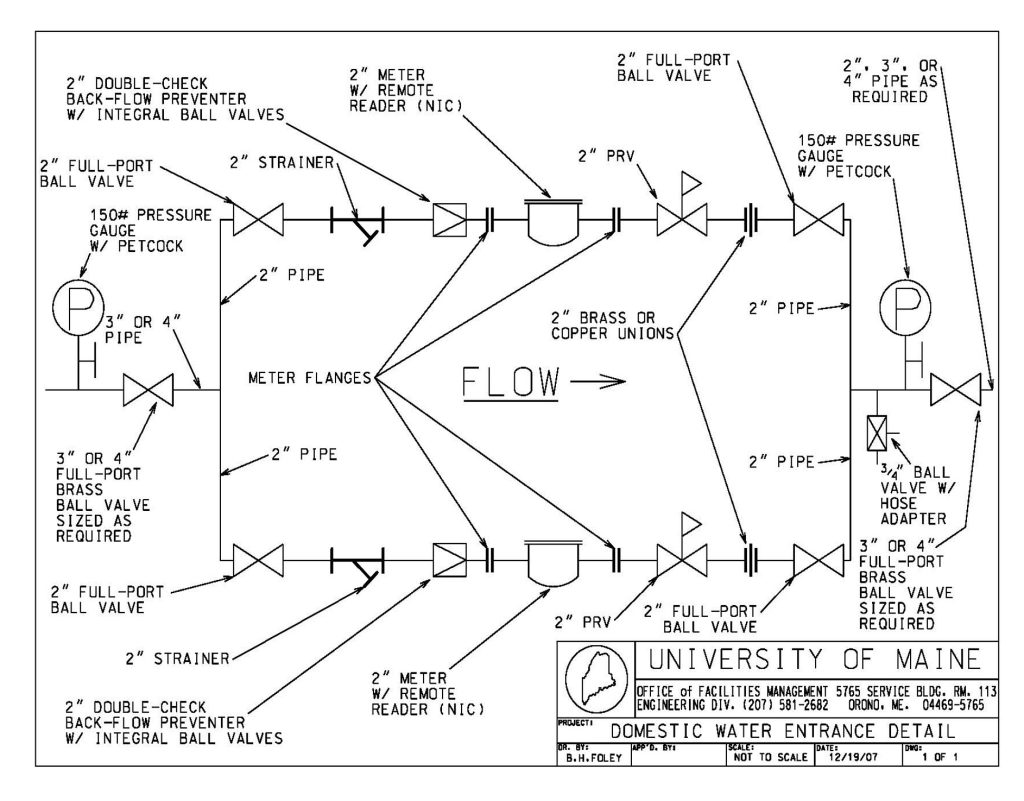
- Specify brass strainer and ball valve at service entrance ahead of backflow preventer. Specify brass ball valve after backflow preventer. All back flow preventers on the water service shall be brass or bronze bodied, and shall be tested and certified by a licensed tester upon installation. Test results shall be submitted to the University of Maine, 5765 Service Building, Orono ME 04469. See UM piping detail dated 12/19/07 “Domestic Water Entrance Detail.”
- Floor drains. Specify piping to sanitary sewer. Acceptable: Josam, Smith, Zurn. Specify screens to minimize insect intrusion.
- Roof drains. Specify piping to storm sewer. Acceptable: Josam, Smith, Zurn.
- Specify floor type slop sinks. Specify first floor slop sinks shall have sand trap solids interceptors.
- Faucets. Specify hard-wired motion-sensor type. Acceptable: American Standard, Chicago, Kohler.
- Specify ball valve and end cap for building drain down on water system.
- Specify low-flow plumbing fixtures shall comply with Maine State Plumbing Code:
- Specify pressure reducing valve on building water service shall be set to deliver 60 to 65 psi at most remote fixture.
- Specify two frost proof sill cocks with vacuum breakers for each building on opposite faces. Acceptable: Zurn Model Z1321C – compression type. Do notspecify Model Z1321 with ceramic disc cartridge.
- Specify all gas piping shall be Schedule 40 black iron pipe or stainless steel. Approved ball valves shall be used at every branch line, at the point where it leaves the main. Valves shall also be used at every fixture termination.
- Specify sump pumps in elevator pits, tied to sanitary sewer. Refer to 14 20 00, Item B.
- Specify a floor drain and pan in drying areas.
- Specify a minimum of one (1) custodial closet per floor with a floor-mounted utility sink.
- Specify floor drains in restrooms and mechanical rooms.
- Specify all acid-resistant drainage and vent piping shall be joined with heat-fusion joints. Mechanical joints shall only be used for fixture connections and shall be exposed and fully accessible. Acceptable: Zurn corrosive waste drainage systems.
- Specify all fume hood stack discharges shall extend a minimum of 10 feet off the roof deck.
- Fume hoods with hot and/or cold water faucets shall be provided with approved pressure-type vacuum breaker outside of fume hood. These shall be accessible, and tested and certified by a licensed tester upon installation. Test results shall be submitted to the University of Maine, Office of Facilities Management, 5765 Service Building, Orono ME 04469. Acceptable: Conbraco, Watts, Wilkens.
- Specify all PVC solvent-welded joints shall be made with a PVC primer-containing purple primer dye.
- Do not specify CPVC water lines.
- Specify conformance with University of Maine piping detail dated 12/19/07 “Domestic Water Entrance Detail.”
- Specify solder used on copper domestic water piping shall be SilverBrite 100. Do not specify 95/5 solder.
- Specify exterior LP gas and natural gas devices shall be protected from damage.
- Specify accessibility to fixtures (i.e. valves, shutoffs) through chases and access panels.
23 00 00 Heating, Ventilating, and Air-Conditioning (HVAC)
1.0.
Mechanical Engineer of Record shall be present for all Air Handling Unit (AHU) start up and during Owner systems training.
2.0.
For projects requiring modifications to existing HVAC systems, the Mechanical Engineer of Record shall identify the impacted systems such that the Owner may perform testing to determine the baseline of the existing conditions.
3.0.
Identify Commissioning requirements early in Design Development phase and coordinate with Owner to develop Commissioning planning.
A. Boilers.
- Specify all cast iron steam boilers shall be designed to be assembled with cast iron or steel push nipples or be constructed with external supply and return headers. For systems requiring process steam or steam for humidification, specify boilers with cast iron or steel push nipples.
- Specify all buildings requiring boilers shall be designed with a ground level boiler room with an outside entrance. Air handling systems shall not occupy the same space as the boiler. The ceiling height of boiler rooms shall be no less than 10 feet. All penetrations for heating, plumbing and electrical pipes from the boiler room into the building shall be sufficiently sealed to prevent contamination of the occupied areas of the building by any fume leakage from the boiler. All penetrations shall be sealed to meet fire code requirements.
- Humidification.
- Buildings connected to the central distribution system that require humidification shall use steam generated at the Central Heating Plant. (University of Maine specific)
- Buildings with their own boiler shall use steam generated for humidification through an exchanger type humidifier.
- Steam boilers. Acceptable: Burnham, Peerless, Smith Mills 350 or 450.
- Specify hot water boilers serving heating systems that incorporate air handling systems, shall have a cold shock prevention system integrated into the boilers’ return system.
- Hot water boilers. Acceptable: Burnham, Peerless, H.B. Smith, Utica, Weil McClain.
B. Air handling systems.
- Air handling systems shall serve only areas of like use. Classrooms, computer labs, scientific labs, lecture halls and offices all have different usage and temperature requirements, all air supply systems shall be designed accordingly.
- Air handling systems shall be designed with consideration given to present and pending indoor air quality standards including American Society of Heating, Refrigerating and Air-Conditioning Engineers (ASHRAE)’s October 19. 2021 Core Recommendations for Reducing Airborne Infectious Aerosol Exposure.
- Air handling equipment shall be designed with adequate access doors and panels in all segments of the HVAC equipment to allow proper cleaning, maintenance and repair of all system components. Filters shall be accessible with a door on each side of the air handlers.
- Air handling equipment shall be located in the building for easy access to all components for service and maintenance.
- Air handlers shall have a mixed air box with mixing vanes designed to eliminate the stratification of outside air and return air.
- Design an air filtration system of pre-filter and final filter. A minimum efficiency for air filtration of 35 percent is expected with all filters being pleated, bag, box, or cell construction. Do not specify fiberglass filters or filters blended with fiberglass.
- Air handling systems shall be designed with sufficient air diffusers to assure quiet and even distribution of air within each ventilated space. Balance dampers shall be installed in the trunk before each diffuser. Dampers that are built into the diffuser shall not be used for balancing purposes.
- Specify electric or pneumatically driven HVAC control actuation devices including valves, VAV controllers and dampers.
- Specify variable air volume systems shall use variable speed drivers instead of vortec dampers. Acceptable: Honeywell, Reliance, Toshiba.
- Air handlers.
a. Acceptable air handlers: McQuay, Trane, York.1. Specify the on-site control system check out shall include the proper operation of all Emergency Medical Services (EMS) control system devices. All thermostats, dampers, freezestat, etc., and the operation of all modes of each AHU shall be proven correct to the satisfaction of the Designer and Owner. The control system shall not be accepted as complete until this has been done. This is the Contractors responsibility and shall be part of the base bid price.b. Acceptable air filters: Airguard, American Air Filter, Farr. - Laboratory fume hood design shall be in accordance with NFPA45. Fume hood exhaust shall discharge at least 10 feet above roof level.
- All HVAC equipment shall be housed within the building envelope.
- Specify Armstrong Duramix for air handlers requiring integral face and bypass coil. (see sample specification document attached)
- As part of submittal process, the contractor shall attain the MAC address for the unit and confirm Dynamic Host Configuration Protocol (DHCP_ compatibility with the University Information Technology (IT) department.
- Specify access doors at each side of dampers of such size to allow ready access to the fusable link.
- If code allows, specify fusable link at ductwork fire dampers shall be capable of 210 degrees.
- As part of the contract and warranty, the AHU manufacturer shall provide a representative for a service call monthly to confirm proper operation of the unit(s). The service calls shall be for the one-year warranty period and commence one month after substantial completion.
C. Testing and balancing.
- Specify a balance report shall be supplied prior to the completion of the project. During the process of training and/or punching out the mechanical system, the balance contractor shall be present with the mechanical designer to check as many grilles as necessary against the balance report to ensure to the Designer and the Owner that the report is correct. This shall be clearly stated in the specifications that this is part of the balance contractor’s bid and any changes brought about by this shall be borne by the Contractor.
D. Air conditioning units – factory start-up.
- Specify AC units shall require start-up by a factory field service technician to ensure the units are properly installed and set-up and operating to design and factory specifications. If the factory field service technician finds any problems with the installation, the mechanical contractor shall take any required corrective measures immediately and be responsible for any subsequent start-up expenses. Any available factory extended warranties shall be purchased with each AC unit. Acceptable AC Units: Carrier, Trane, York.
- Specify a minimum of eight hours of training by the factory field service technician during the start-up procedure for the University’s HVAC technicians with Designer present.
- As part of the contract and warranty, the AC unit manufacturer shall provide a representative for a service call monthly to confirm proper operation of the unit(s). The service calls shall be for the one-year warranty period and commence one month after substantial completion.
E. Hot water heating and chilled water cooling.
- Specify hot water heating and chilled water cooling systems shall be protected from freezing with a 50 percent by volume solution of propylene glycol.
- Specify isolation ball valves and drain stations on the supply and return sides of each heating unit (unit heaters, baseboard radiation, VAV reheat coils, main branch lines, etc.) and a drain valve for each unit. A balance valve shall not be considered as an isolation valve.
- Specify rising stem gate isolation valves on the suction and discharge side of each circulation pump.
- Specify check valves on the suction or discharge side of each circulation pump.
- Ball valves, with stainless ball, stem and seat. Acceptable: Apollo, Nibco, Stockham, Watts.
- Specify welded or threaded pipe on chilled water and hot water heating lines.
- Gate valves, with rising stem. Acceptable: Crane, Jenkins, Nibco, Stockham, Walworth.
- Pumps. Acceptable: Bell & Gossett, Taco, Weinman.
- Anti-freeze. Acceptable: Dow Frost, No-Burst.
- All pumps shall be floor-mounted with 2’ clearance on all sides.
F. Steam traps.
- Thermostatic traps. Acceptable: Armstrong TS2, Barnes & Jones models 122 &134, Sarco.
- Float & thermostatic traps. Acceptable: Barnes & Jones, Sarco, Armstrong.
- Bucket traps. Acceptable: Armstrong, Barnes & Jones, Sarco.
G. Gate and globe valves.
Specify 150#, os&y for flanged valves and rising stem for threaded valves. Acceptable: Crane, Nibco, Stockham, Walworth.
H. Ball valves.
Do not specify ball valves for steam service. 150# steam-rated with stainless steel ball, stem and seat, RTFE seat and packing, and latch lock handles for hot water heating service. Acceptable: Apollo, Nibco, Stockham, Watts.
I. Steam pressure reducing valves.
Specify 50# entering steam – pilot operated. Acceptable: Leslie, Masoneilan, Spence.
J. Fittings cast iron and malleable.
Acceptable: Flagg, Stockham, Ward.
K. Flange gaskets.
Acceptable: 150# API 601 Flexitallic, Leader, Parker.
L. In-line strainers and check valves.
Acceptable: Crane, Stockham, Walworth.
M. Pressure and temperature gauges.
Specify pressure gauges on all chilled and hot water pumps shall be liquid filled. Acceptable: Ashcroft, Marshalton, Trerice.
N. Air eliminators.
Acceptable: Spiro-vent, Armstrong, Sarco, Taco.
O. Steam-heated semi-instantaneous water heater.
Acceptable: Ace, Armstrong, Patterson-Kelly.
P. Expansion joints.
Acceptable: ADSCO, Advanced Thermal, Yarway.
Q. Condensate pumps.
Acceptable: Dunham Bush, Skidmore, Weil.
- Specify condensate pumps shall be duplex with alternating operation.
- Specify condensate pumps shall be equipped with failure alarm contacts. The alarm contacts shall be wired to the Energy Management Control System for reporting all pump failures to the head-end computers located in the HVAC Shop.
- Specify condensate tanks shall have a temperature sensor installed by Johnson Controls, Inc. or Honeywell International, Inc. This sensor shall be wired to the Energy Management Control System for continuous monitoring at the head-end computers located in the HVAC Shop. A high limit alarm point shall be programmed into the system.
R. Boiler feed pumps and tanks.
- Specify boiler feed tanks shall be equipped with duplex alternating pumps with alarm contacts. A temperature sensor shall be installed in the tank. The alarm contacts and temperature sensor shall be wired and programmed as described in the specifications.
- Specify boiler feed tanks shall be sized appropriately with consideration given to boiler, pipe, heat exchanger, heating coil, and radiation capacity. Acceptable: Dunham Bush, Skidmore, Weil.
S. Unit and cabinet heaters.
- Specify unit and cabinet heaters used in conjunction with steam heating systems shall have heating coils specifically designed for use with steam, T/B connections. Acceptable: Beacon-Morris, Dunham Bush, Modine, Trane.
T. Building fin tube radiation.
Acceptable: Beacon-Morris, Ted Read, Trane.
U. HVAC control systems.
- The University has two fiber optic trunks available for Energy Management Control Systems. One fiber optic trunk is dedicated to Johnson Controls, Inc. system network, the other to Honeywell International, Inc. system network. The networks are terminated at the head-end computers located in the HVAC Shop. All controls work shall be coordinated with the University IT department prior to installation.
- Specify HVAC systems shall be operated and controlled by either the Johnson Controls, Inc. system or the Honeywell International, Inc. system through the appropriate existing fiber optic network located in the HVAC Shop. The systems shall be DHCP capable.
- Specify new control systems shall have an on-site, hand-held device that allows access to the fiber optic network for building-to-building communications and operations.
- Specify programming shall be consistent and compatible with the existing systems. All status and control points shall be programmed to be accessible from the head-end computers in the HVAC Shop.
- Specify HVAC control points shall be accessible from the head-end computers located in the HVAC Shop, through both access groups and dynamic system graphics. The graphics shall accurately depict the HVAC system with dynamic status and interactive control and adjust points. Access to scheduling shall also be available through system graphics.
- Specify HVAC Control Systems shall be designed by applications engineers employed by Johnson Controls, Inc. or Honeywell International, Inc. and installed and programmed by either Johnson Controls, Inc. or Honeywell International, Inc. technicians. Installation may be sub-contracted if all work is directly supervised by Johnson Controls, Inc. or Honeywell International, Inc. and responsibility for the installation and programming is held by Johnson Controls, Inc. or Honeywell International, Inc.
- Specify HVAC control actuation devices (valves, dampers, VAVs, etc.) shall be electric or pneumatic.
- Specify minimum outside air shall be re-set from a carbon dioxide sensor to be located in the return air duct.
- Specify air compressors for pneumatic controls shall be equipped with an electric auto-drain.
- During construction if pneumatics are needed, the control company must supply a temporary compressor. The temporary compressor shall remain in use for the duration of the construction period, at which time the building will be connected to its permanent compressor.
- Specify hot water heating and domestic hot water derived from steam converters shall have pneumatic receiver/controllers with remote set-point adjustment by the Johnson Controls, Inc. system or the Honeywell International, Inc. system located in the HVAC Shop.
- Specify boilers shall not be controlled by the Energy Management Control System, but shall be monitored for temperature, pressure and alarms at the head-end computers located in the HVAC Shop.
- Specify the use of the specifications for control systems check out and start up supplied by Project Engineer.
- Specify 24 hours of on-site technical and operational training for the University’s HVAC staff at project completion. Acceptable: Honeywell International, Inc., Johnson Controls, Inc.
- Specify the contract-provided HVAC control compressor shall be installed on the date of substantial completion.
- As part of the contract and warranty, the controls manufacturer shall provide a representative for a service call monthly to confirm proper operation of the unit(s). The service calls shall be for the one-year warranty period and commence one month after substantial completion.
V. Exhaust ventilation.
- Specify all mechanical spaces shall be ventilated.
- Specify all custodian closets shall be ventilated.
W. Where previous equipment is abandoned in place, specify that such equipment will be disconnected and locked out.
26 00 00 Electrical
- Specify LED fixtures (either 3500 or 4100; coordinate with FM per project). If unable to use LED fixtures, shall be supplied with T5 or T8-41K lamps and electronic energy saver ballasts.
- Light switches. Specify specification grade, ivory color. Consider occupancy sensors connected to light switches.
- Receptacles.
1. Specify specification grade, ivory color.
2. Emergency power receptacles shall be specification grade and be red color with cover as determined by coordination with FM. - Wall plates. Specify specification grade, stainless steel or nylon ivory.
- Specify 120 volt, single-phase, 15 and 20 ampere receptacles installed within 6 feet of sinks shall be GFCI receptacles. Do not specify receptacles of higher voltages and/or amperages within 6 feet of sinks.
- Electrical panels. Specify panelboards with bolt-in breakers only. Acceptable: Cutler Hammer, GE, Siemens, Square D.
- Specify electrical panelboard covers shall be door-in-door or hinge-to-front type.
- Specify electrical panels installed outside mechanical rooms and electrical rooms shall have locking doors.
- Specify electrical panels shall be marked and breakers labeled per NEC. Permanently post a copy of the power one-line riser diagram in the Main Switch Room as close to the main switchboard as possible.
- Fire Alarm System. Specify wiring shall be as required by Gamewell standards. Acceptable: Gamewell only.
1. The Owner shall review and approve the documentation of the fire alarm program.
2. Location descriptions for fire alarm addresses shall be approved by the Owner prior to programming.
3. Specify fire alarm smoke detectors in egress corridors.
4. Specify red jacketed multi-conductor cables shall only be used for fire alarm installations. - Specify 120 volt convenience receptacles shall be installed:
1. In corridors at maximum 40 foot spacing; and,
2. In stair towers, at lowest level and at every level of the stair tower. - Conductor color coding.
1. Specify conductors for 208/120 volt systems shall be color coded as follows:a. Ungrounded conductors shall be black, red and blue.
b. Grounded conductors shall be white.
c. Equipment grounding conductors shall be bare, green, or green with one or more yellow stripes.2. Specify conductors for 480/277 volt systems shall be color coded as follows:a. Ungrounded conductors shall be brown, orange, and yellow.
b. Grounded conductors shall be gray.
c. Equipment grounding conductors shall be bare, green, or green with one or more yellow stripes. - Do not specify key operated switches. Where necessary, key switches for specific devices or equipment are acceptable. Key switches are to be avoided for lighting controls. Stairwell lighting is to be controlled by occupancy sensors.
Specify electrical conductors shall be copper only.
Specify secondary service conductors running from the service transformer to the building service disconnect shall be installed in rigid galvanized steel conduit or covered by concrete PVC conduit.
Specify exterior transformers shall be protected from damage based on hazard assessment for the location (i.e. bollards).
Specify termination of copper secondary conductors to the secondary lugs of the service transformer shall be by means of 2 hole un-insulated long barrel copper compression terminals, such as Burndy Type YA(__) – 2N, or equivalent. These terminals shall be bolted to the transformer secondary lugs using an approved method and hardware. - The University of Maine Electrical Shop will furnish and install the service transformer and pad as well as the primary conduit and conductors.
- Specify emergency generators shall be protected from damage based on hazard assessment for the location (i.e. bollards and overhead protection).
- Specify revenue grade Shark multi-function power and energy meter manufactured by Electro Industries shall be provided in the main switchboard. Owner to determine appropriate model.
- Specify ample raceways and wire ways to allow wiring from lectern to equipment.
- Provide scale plan drawing showing all conduit runs and paths.
- Where previous equipment is abandoned in place, specify that such equipment will be disconnected and locked out.
26 50 00 Interior Lighting
- Specify interior lighting installed above 8 feet shall be installed in locations where clear and unobstructed access, to include around non-movable chairs, seats, desks, lab counters, etc., is available via ladder or lift.
- Specify interior lighting installed below 8 feet shall be protected against breakage.
- Specify lights in stairwells shall be wall-mounted at ±8 feet above floors/platforms.
- Specify lighting control devices that are readily available. Package lighting control systems are not desired.
26 56 00 Exterior Lighting
- Specify exterior site lighting and exterior lighting on buildings shall be photocell-controlled with lighting contactors. Photocells shall not be installed under eaves. Photo cells shall be readily available item and not specifically connected to any lighting control system. The location of the photo cell shall be coordinated with Owner.
- Specify exterior lighting shall not be connected to or controlled by any Johnson Controls, Inc., Honeywell International, Inc. or other energy management control system.
- Specify exterior luminaries shall be 100 percent cut-off type.
- Specify exterior lighting shall be installed in locations where clear and unobstructed access is available via ladder or lift, to include around entrances, landscaping, transformers, etc.
- Specify where wall pack mounted lighting is used it shall be accessible via portable ladders and/or aerial lifts.
- Specify illuminated path shall be provided to all large rooftop equipment from the roof access point. Controls shall be located at roof access point and shall have indicator lamp integral to the control indicating when site lighting is on or off.
- Walkway lights to be Kim model Warp 9 LED lights and accessories.
27 00 00 Communications
A. Use Section 27 00 00, Communications where applicable. (document attached)
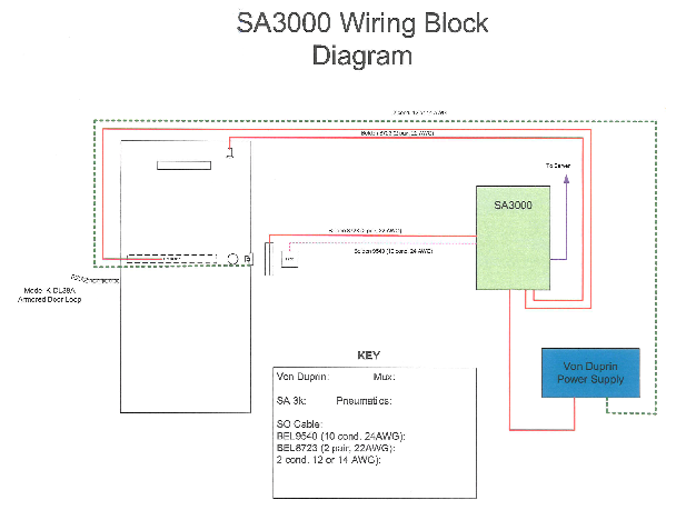
28 13 00 Access Control
- Specify card entry system at all entrances. Acceptable: Blackboard.
- Specify recommended wire, type, use, series, run location, and maximum length.
Recommended Wire Wire Type Usage Series Run Location Maximum Length 1 pair 14 or 12 AWG latch SA2k/3k SA2k to Door Crashbar 300’/500’ Belden 8723 2 pair 22AWG each pair shielded point SA2k/3k SA2k to Door Frame n/a Belden 8723 2 pair 22AWG each pair shielded request to exit SA2k/3k SA2k to Door Crashbar n/a Belden 8723 2 pair 22AWG each pair shielded handicapped exit SA2k/3k SA2k to Handicap Paddle n/a Belden 8723 2 pair 22AWG each pair shielded swipe SA3k SA3k to swipe n/a` Belden 9540 10 condr 24 AWG shielded prox SA3k SA3k to Prox. Sensor 100’ Belden 9541 15 condr 24 AWG shielded prox SA2k Weigand Board to Prox. Sensor 100’ Belden 9541 15 condr 24 AWG shielded prox SA2k Weigand Board to Prox. Sensor 4000’ - Specify control and power to door. Acceptable: Model K-DL38A Armored Door Loop.
32 10 00 Bases, Ballasts, and Paving
- Specify bituminous pavement roadways. Coordinate width with Grounds Shop for associated plowing equipment.
- Specify a safety zone shall be maintained between parking, walkways and buildings.
- Specify woven geotechnical fabric under all paved surfaces.
- Specify 9’ x 18’ parking spaces with 24’ drive aisle typical. Do not use angled parking.
32 16 00 Curbs, Gutters, Sidewalks, and Driveways
- Specify bituminous pavement sidewalks. Coordinate width with Grounds Shop for associated plowing equipment. Do not use concrete sidewalks.
- Specify a safety zone shall be maintained between parking, walkways and buildings.
- Locate sidewalks along roadway curbing. Do not provide lawn esplanades.
- Specify vertical granite curb. Do not use sloping curb.
- Locate sidewalks along roadway curbing. Do not provide lawn esplanades.
32 30 00 Site Improvements
- Specify new buildings shall consider a truck accessible loading dock consistent with the building’s use.
- Specify raised loading docks shall have stairs with handrails.
- Specify loading dock drives shall not be used as parking areas.
- Specify loading dock overdoor doors shall be protected from the elements via a portico or similar structure.
- Specify overhead or double door access to loading dock from building interior. Where possible, create a service entrance to the building for maintenance considering proximity to service vehicle parking, mechanical rooms, and elevators.
- Consider operational issues from snow and ice, including plowing, staging, and removal.
- Specify 9’ x 18’ parking spaces with 24’ drive aisle typical. Do not use angled parking.
- Specify all exterior signage by Owner.
- Specify any outside equipment must be placed in such a way as to avoid damage from falling roof ice and snow.
32 90 00 Planting
- Specify lawn restoration by Owner.
33 10 00 Water Utilities
A. Water utility distribution piping.
- Specify pipe and fittings shall be Ductile Iron Class 52 conforming to ANSI 21.51.
- Specify trench shall be laying condition “B” (flat bottom trench without blocks and with compacted backfill). Pipe bedding material shall be 3/4” crushed stone, 6” below pipe to 6” above pipe.
- Specify thrust blocks shall be cast-in-place wherever possible.
- Specify fittings shall be rodded where necessary to prevent movement and leakage.
- Specify a corporation and blow-off line shall be installed at or near the point of connection with the main. The blow-off shall be completely removed and the corporation either plugged or capped after testing and chlorination is successfully completed.
- Specify a bacteriological water test shall be made by an acceptable laboratory, with test results submitted to the University of Maine, Office of Facilities Management, 5765 Service Building, Orono ME 04469.
- Specify a hydrostatic pressure test to 200 psi or 1-1/2 x working pressure, whichever is greater, shall be performed.
- Specify valves shall be installed on all three sides of a “T” connection.
B. Fire hydrants.
- Operating direction open clockwise. Acceptable: Mueller Super Centurion 250.
- Operating direction open counter-clockwise for all system building valves.
C. Domestic Water Entrance Detail.
- See attached detail.
33 30 00 Sanitary Sewerage Utilities
- Specify outside clean-outs exterior to building if no manhole in close proximity.
33 40 00 Storm Drainage Utilities
- Specify outside clean-outs exterior to building if no catch basin in close proximity.
33 56 00 Fuel-Storage Tanks
- Specify above ground oil tanks in buildings shall be of double-walled construction with 110 percent secondary containment capacity.
University of Maine Campus Design Criteria Attachments
The following items are referenced attachment to the Campus Design Criteria.
- Structural Statement of Special Inspections
- Section 15710 Heat Exchangers – Face & Bypass Heating Coil Packaged System
- Domestic Water Entrance Detail
- SA3000 Wiring Block Diagram
(Revised March 28, 2022)